Welcome back
Today I would like to finally tie together the stuff I’ve been talking about in previous posts about the structure of the game engine, with images and diagrams! Some of this will probably feel obvious, but I think it’s an interesting topic to discuss none the less, so that’s why it’s here and not in a weekly update post. Feel free to skip ahead to the diagram of the game engine at the end, this post is just going to explore how it was constructed and what I find interesting about the process. These diagrams may not be completely accurate, as I’m sure I will learn more about the game structure the more of it I translate, but for now I think the big one at the end is representative of my current understanding of the game.
Preamble
Before I talk about conceptually organizing this sort of thing, I should explain what that means and why it’s important.
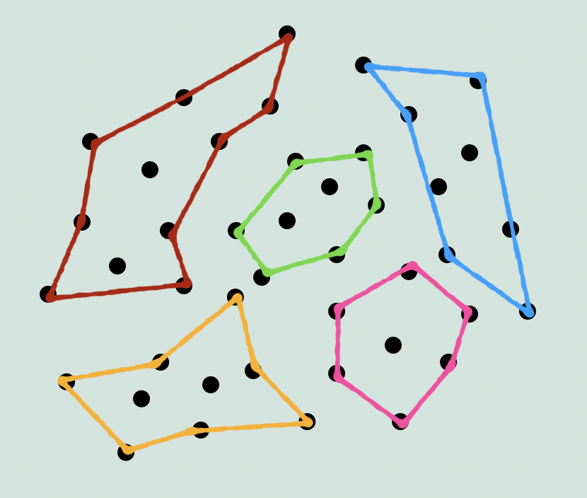
Any kind of game engine is going to be a complex system. For every frame, it has to convert user input into an intricate mosaic of art assets that are each the result of all kinds of overlapping subsystems. To perform this magic trick, almost any given place within the system is connected to several others in some way. Maybe it’s direct, like a function call, or maybe it’s indirect like a variable whose value here is determined elsewhere. Or maybe it’s a piece of data which references another piece somewhere else, which in turn has a reference to a function in yet another location. You can think of it a little like a brain. Where each neuron is connected to others, and every frame the entire network lights up with electrical impulses as information moves and changes from one place to another. When you look at the engine as a whole, you can see the pulses going in and out in all different directions, but trying to identify the patterns and movement will be confusing from any perspective. You need a way not only to understand the meaning of the code at a small scale (see: blog post about translating assembly), but also to understand the language of the engine itself. How the components talk to each other, so you can see patterns instead of noise. Because within the noise, is a unique flow of logic from input to output, which is, more so than the specifics of the code itself, what makes up the game. Basically we start with a web of neurons that form a general shape, but we want to see the distinct regions and connections like this:
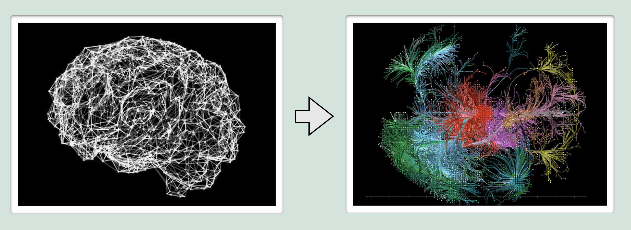
So, given the task of translating the engine, you need a way of conceptualizing the connections and movement of information at a macro scale, so that you can develop a strategy and not get lost following one thing to the next on a smaller scale. You can’t just pick a random point within the network and expect to understand what’s going on, context is crucial. So the strategy has to minimize the amount of connections at any given time that lead to places you don’t know about yet. Or to put it another way, you need to identify and draw the outline of each component before you start filling them in.
Having the source code puts you at a big advantage, even if it’s entirely in assembly. Because at the very least, you can see everything that is in the engine, and even if the organization of the different components isn’t perfect for understanding the connections, there is at least some kind of organization you can see right away.
Getting Started
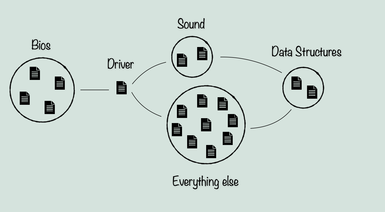
So, assuming you have the source code, the first step is to take stock of what you have. In this case, we have about 45 files with names of varying levels of ambiguity. Everything from ‘Boot’ to ‘cyc’. From here, we can start by categorizing them by their name and if needed, a quick skim through the file. From this we can deduce that a small percentage of the files are related to some kind of hardware level interaction, like a bios. For example ‘Boot’, ‘Load’, and ‘Dos’ are pretty likely to be run before the game itself starts. For a game on the Apple IIGS, we have to keep in mind that unlike a console, the environment to run the game in is not there by default. The Apple IIGS by default is set up for running smaller scale programs over top of the operating system. But for a game like The Immortal, which needs all the resources from the computer that it can get, it has to start with things like: setting up the memory it will be using, loading in the game code and the assets through ProDOS, and telling the Apple IIGS how it will be drawing the screen. So for now we can set aside those files as not being directly related to the game code. The exception being the well named file, ‘Driver’. This file clearly has these bios type interactions, but also contains routines that the game code needs for interacting with the hardware. Driver has palette routines for example, but they are not concerned with how the palette is being used in game, their job is to apply the correct palette data to the Apple IIGS palette memory, and tell the computer how to use it.
Next we can look at the other names and make some general groupings. For example ‘Array’ and ‘QArray’ have recognizable names, and from a skim through the files, we can see that they are more or less what they say they are, implementations of data structures (Basically just types of Lists, ie. resizable arrays and in the case of QArray, a Queue-like system for push/pop methods). Likewise, ‘Sound’, ‘Songloader’, ‘Macros’, and ‘Compression’ don’t leave much to the imagination, and can be easily grouped. The rest however, we will have to look further into. For now though, we can start putting together the basic model. We know that bios-type files are the lowest level of abstraction in the engine, and are not likely to call or interact with anything above ‘Driver’.
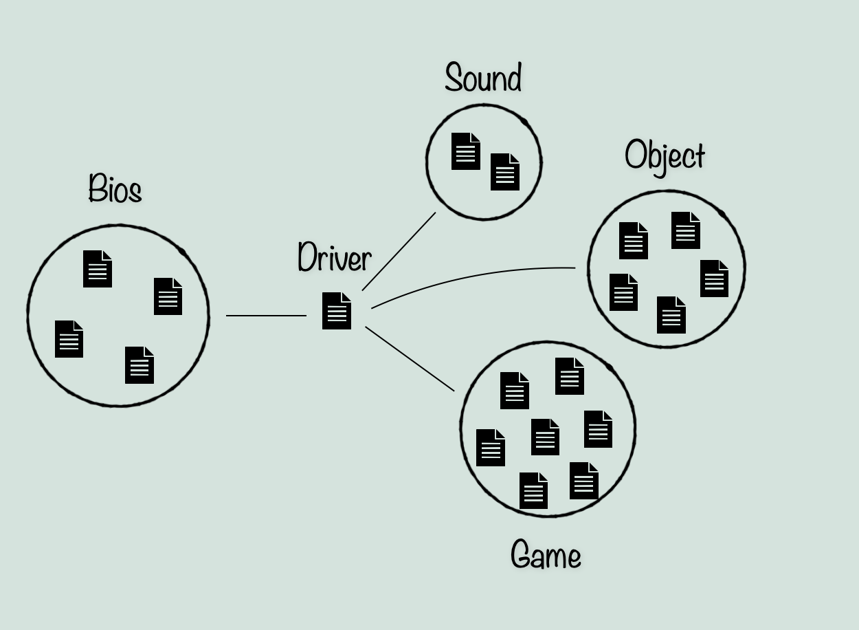
Next we can see if any other files fit into obvious categories from a quick look through their code and any comments that might explain. From this, we can separate the rest of the files into generally two categories. I’ll call them Game and Object. Game refers to any files that are not obviously describing a single data type. While object refers not to the modern definition of Object in programming, but simply a file describing a single data type, which could be placed in an environment like an object. This includes ‘Monster’, which is pretty clearly describing enemies (and also the player character interestingly enough).
Now although much of the bios files are not relevant to ScummVM, there are lots of definitions within which we will be using, so we can for the moment leave them in the diagram. The Data Structure files however, can be left out. This is because they do not seem to be unique from what they are meant to implement, and as a result there is not much point in translating them instead of using the equivalent structures in C++ unless I find something special about them in the future.
With this, we have a very basic idea of what makes up the game engine.
Finding an entry point
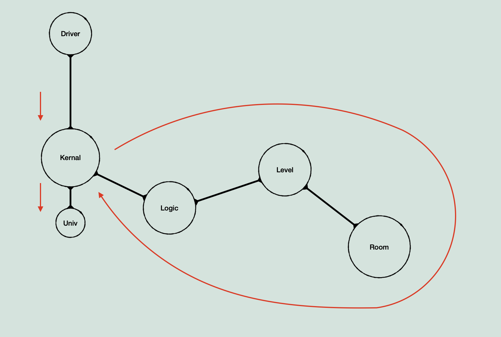
Now that we have grouped the files, we can narrow the search field and start to identify key components. My first step was to look through the bios files to get an idea of what hardware interaction needs to be simulated, what can be ignored, where the main entry point for the engine is, and what the memory model looks like. Luckily, most of this is pretty easy to find. The entry point can be found a few different ways. Either by tracing a path all the way from the Loader file of ProDOS, or by moving backwards from the main frame loop (if you start your search in kernal instead of driver), or by manually searching through Driver, which we have already identified as being the interface between the game engine and the Apple IIGS. Either way, I found that ultimately the relevant starting point of the engine is the routine in Kernal, jumped to by Driver, called ‘Main’. Reading through the routine, we can determine that it is the main over-arching frame loop of the engine by a few things. It initializes the global memory space, calls several asset loading routines, and then enters a loop with no immediately visible exit. Judging by the names of routines being called, the loop can skip the screen drawing routines if the game logic is ‘frozen’, and the loop also checks input several times. The other notable things are that it calls ‘logic’, ‘drawuniv’, and ‘copytoscreen’, all of which imply this routine follows the expected main loop logic of: check input -> run game logic -> construct image -> send image to whatever video buffer is used by the Apple IIGS hardware. So, what this tells us for the engine model, is that Kernal is going to be one of the primary nodes that data moves through, and will likely be connected to both the input (game assets and player input), and the output (audio and video out).
Exploring the game engine
With the main loop identified, I started the translation. I mentioned before that I was thinking of it in terms of ‘inside out’, but it’s a little bit more complicated. My basic strategy has been to follow the flow of logic, identifying where it branches and where the main path continues (the main path being the ‘inside’). And along the way identifying the larger nodes in the chain, from which a skeleton can be started. What this means in practical terms, is that I took a brief look in to each of the routines called in that main loop, taking notes on what leads to larger components and what has dead ends. For example, following the call to ‘logic’ quickly adds more and more branches into larger areas, so I noted that it is the entry point of the main game structure. While on the other hand, ‘copytoscreen’ hits a dead end quickly in Driver, ultimately finalizing the array of bytes in memory representing the screen, which the Apple IIGS will use to display the game. The initialization routines are a little more complicated, as they do lead to branching paths. However those hit dead ends as well, and I could note the general purpose of them. So now we can start building a really simple model based on Kernal.
- Init
- Load assets
- Using ‘LoadIFF’
- Using ‘Compression’
- Using ‘LoadIFF’
- Main loop:
- Check input
- Run game Logic
- Construct image
- Display palette
- Display image
From here, we can skip over the process of translating and exploring, as I’ve gone over some of the details of that previously, and this post is about the engine model. We can now see a model of the engine taking shape (the red line being the main game logic path):
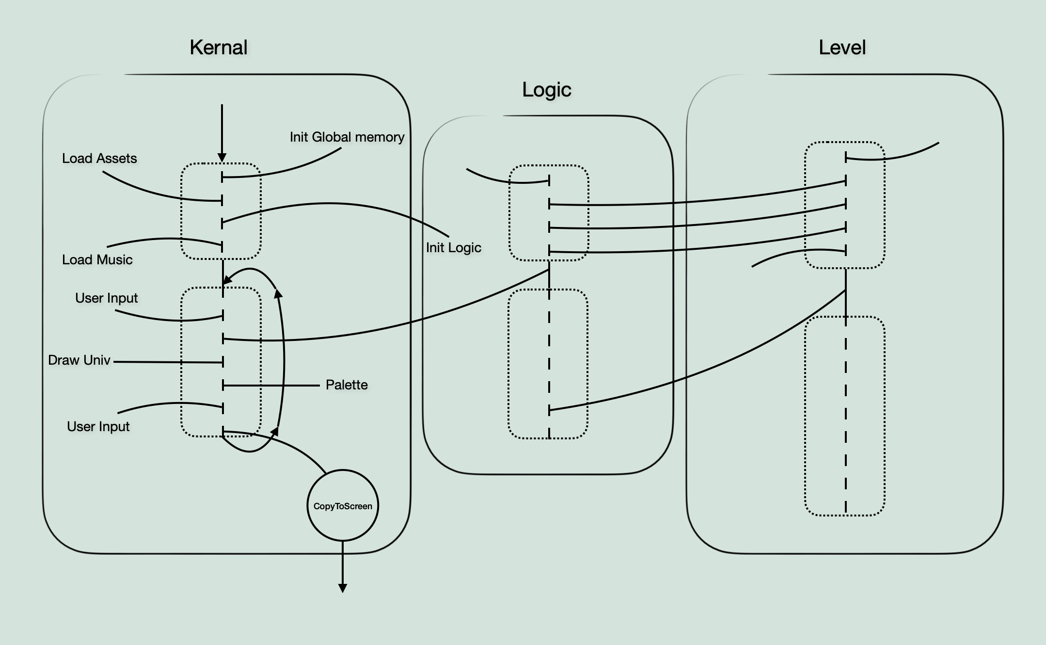
In terms of exploring however, I should also note the other thing I’ve mentioned a few times, which is that I have been working on it in terms of ‘layers’. What I mean by this, is that once I identify a complete skeleton, and the entry point from it into the next section of branching routines, I consider that to be a ‘layer’. Sort of like a file directory, where you have X number of files, and one of them is a sub-directory. Instead of immediately making the skeleton of the sub-directory as soon as I see it, I try to finish filling out the current directory skeleton. This way I hopefully have a more complete picture of all the data types being worked with at a given time by looking at everything at the same level of abstraction at each point. This methodology is intended to make sure that I don’t get lost following a long chain of game logic until I end up having to piece more and more together for anything I look at because I didn’t look fully at something in a previous part. Also of note, I re-evaluated the layers once I factored in scope, simplifying them for the general model.
One other thing to mention at this point is the idea of a ‘skeleton’. It’s a word that’s used a lot so I wanted to make a diagram that visualizes the idea. This sketch shows the parts of the main loop in kernal, but I also included bits of logic and level to show how they connect together.
Considering Scope
Okay, so for a while I was filling out the skeletons of kernal and logic, as well as translating important routines. But it was hard to get a sense of the overall size and interconnections of the game. This is where scope comes in. The next step I took was to go over every file in the source code and look at what it actually is, in relation to the other files and mental model of the game at the time. To do this, I started drawing diagrams on paper that simply showed which files were connected to which others, and what type of file it was (ie. data that is used in other files, or code). This produced something approximately like this:
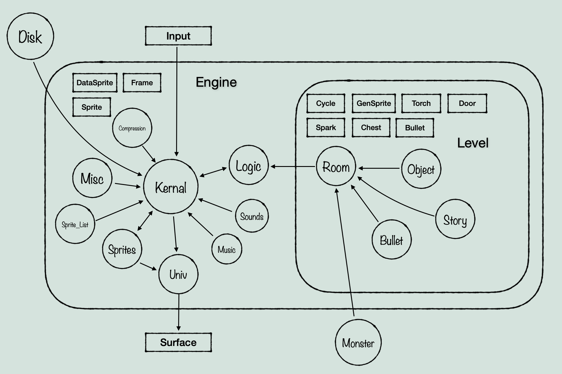
(Be glad I didn’t include my actual paper sketch, it is not legible)
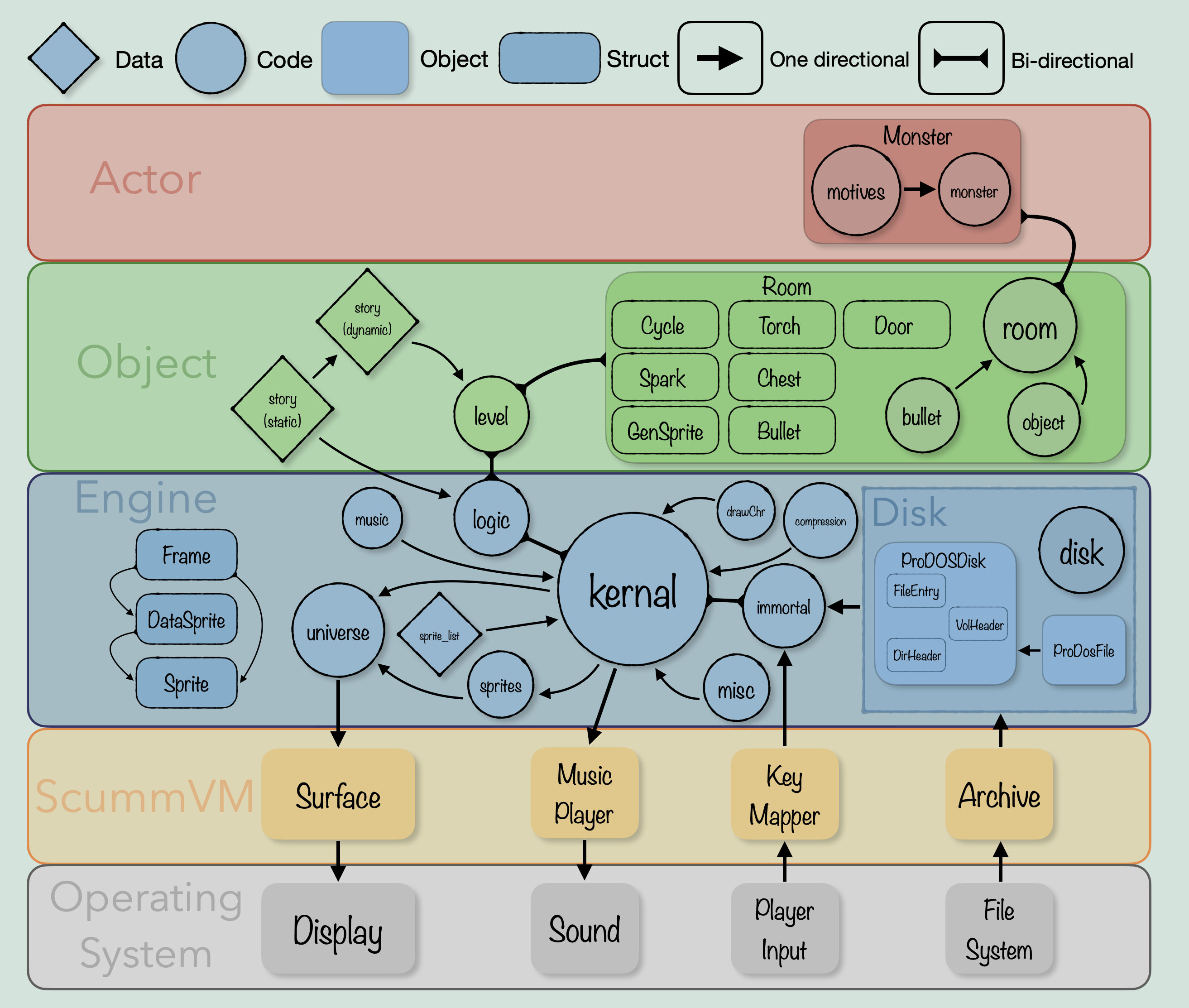
With something tangible to work with, I evaluated the scope of different data types within the files, and decided on data structures that fit the amount of code and structure actually associated with each. Mostly they ended up being structs for now, with Room and Monster being the only full objects. I decided that Room should be an object because it contains several ‘objects’ that only exist within the instance of a Room, and are handled within that scope, with level and logic calling functions meant to ‘get’ information about the status of those data types from the Room object. Monster seems fairly clear as an object, as it has a large set of functions that act only on it, and the game uses similar functions to ‘get’ information about it.
Putting it all together
Finally, we can put all of this together into a diagram that divides the engine into layers representing more or less the level of abstraction away from the main engine running code, and shows the flow of logic in/out of each component of the engine.
Model with function names
And this is a diagram of a single layer in terms of actual function names and whether they are complete or not (this sketch may be a bit behind what I’ve translated, I put it together a little while ago so it is likely missing some functions):
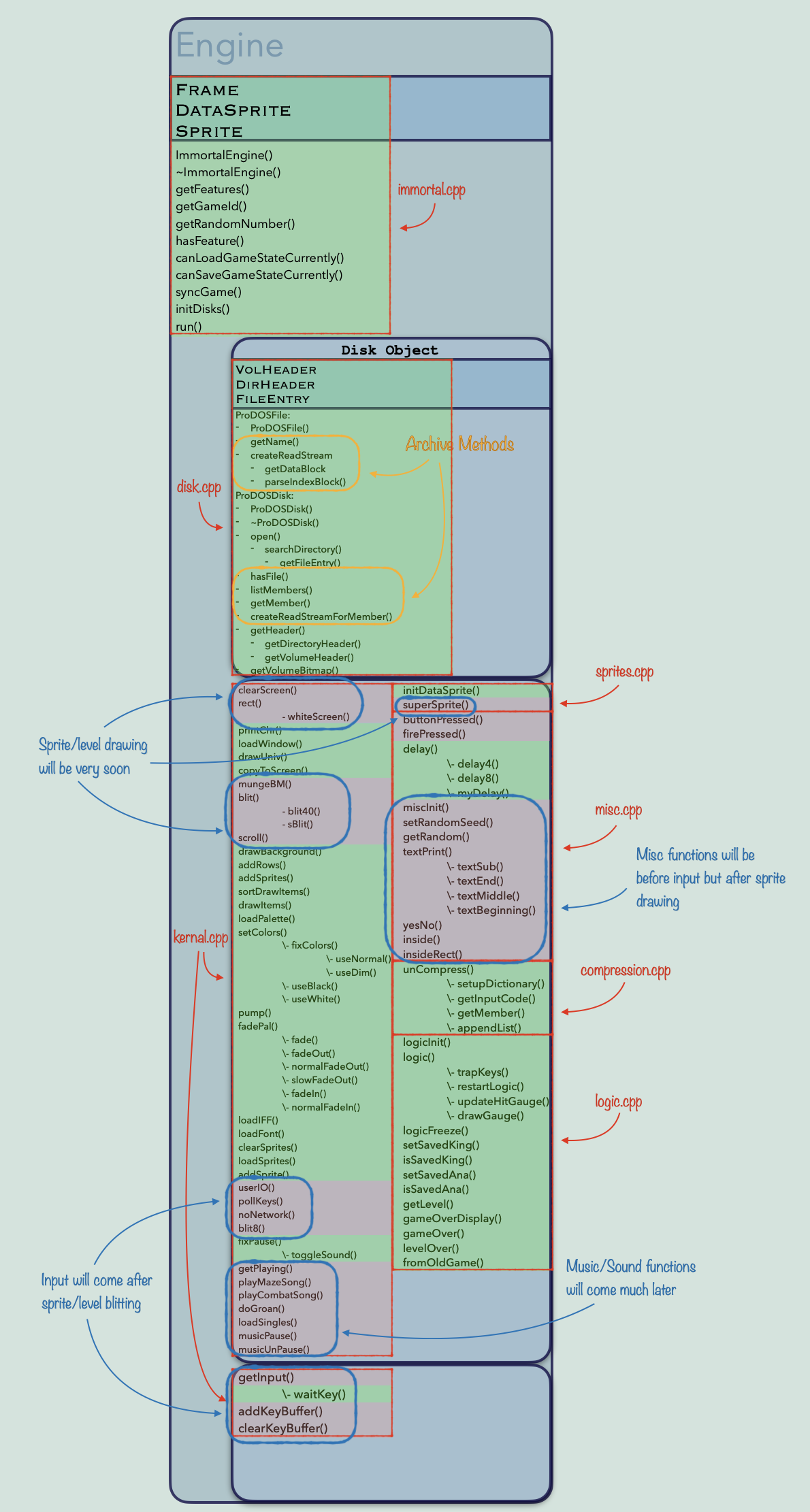
Alright, if you took the time to read all of that, thanks! I appreciate it.
I will have a regular update post as usual this sunday/monday about the actual code and what I’m working on specifically. I had just been meaning to put some of my thoughts on this topic, and diagrams I had made for myself along the way, into a post because I find it really interesting, and maybe someone else out there will too!
